
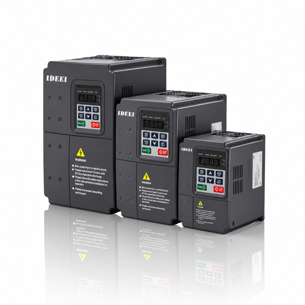
Size a pump-station drive arrangement from individual motor requirements and operating scenarios, not just the sum of nameplate kW. A duty/standby station and a station that runs several pumps together can have the same installed power but different control, supply and availability requirements. This blank schedule helps a buyer define those requirements before asking for models or prices.
Keep three questions separate
- Each drive: which motor does it serve, and what continuous current, overload duty and site derating apply?
- Station supply: which loads can operate or start together, including auxiliaries and any backup-source constraints?
- Control and availability: what happens when demand rises, a pump is unavailable or the source changes?
Do not assume a standard VFD is approved to control several motors, alternate between motors or perform cascade control. The proposed architecture, interlocks, protection and any output switching require model-specific engineering. This worksheet does not authorize switching a motor on a running drive output.
One row for each motor
| Record | Pump A | Pump B | Pump C / other |
|---|---|---|---|
| Nameplate voltage, phases, frequency and motor type | ____ | ____ | ____ |
| Rated current and kW / HP convention | ____ | ____ | ____ |
| Required flow, head and pump curve | ____ | ____ | ____ |
| Duty, starts and operating hours | ____ | ____ | ____ |
| Cable length, installation and applicable filters | ____ | ____ | ____ |
| Role and allowable outage | Duty / assist / standby; ____ | ____ | ____ |
Record temperature, altitude, enclosure, cooling and source details separately. Mark missing values as unknown and obtain the motor or pump manufacturer’s data. A fixed percentage added to kW cannot replace current, compatibility and duty checks.
Describe operating scenarios
| Scenario | Fill in before quotation |
|---|---|
| Normal demand | Which pump runs; target flow/head; other running loads |
| Peak demand | Which pumps run together; operating points and duration |
| One pump unavailable | Required remaining service; permitted reduction or interruption |
| Starting and stopping | Proposed sequence, simultaneous starts allowed, pressure constraints |
| Backup supply or source transfer | Essential pumps, transfer interruption and source limits |
These are prompts, not a designed station. Do not assume the standby pump always remains off, or count every installed motor as continuously loaded. State the scenarios explicitly and have the hydraulic and electrical design checked together.
What the supplier should return
- A proposed drive-to-motor arrangement and the operating assumptions used.
- Exact model output-current ratings, duty and applicable derating, rather than catalogue kW alone.
- Items outside the drive: panel protection, contactors or bypass if proposed, sensors, interlocks, controller and commissioning responsibility.
- A list of missing information and any restrictions on the requested operating modes.
Upstream supply or generator sizing needs its own electrical assessment; it is not obtained by copying the drive output rating. Likewise, changing drive size cannot establish adequate water delivery without the pump and system curves.
Frequently asked questions
Must I add the standby pump’s kW to every operating case?
No. Record whether it operates in that case. Installed capacity and simultaneous operating load answer different questions.
Can one VFD serve all pumps?
Only if the exact arrangement is engineered and approved for the equipment and required protection. Do not infer this from the drive’s kW rating.
For an individual solar pump, see the motor-and-drive sizing guide. For a station quotation, send the completed schedule to IDEEI.
Technical context: Danfoss on variable-torque applications distinguishes centrifugal applications from other load types. That background does not establish cascade or multi-motor capability for an IDEEI model. This blank schedule is an editorial tool, not measured project data.